Local Area Networks: The Spanning Tree Protocol and Virtual LANs
Warning
This is an unpolished draft of the second edition of this ebook. If you find any error or have suggestions to improve the text, please create an issue via https://github.com/obonaventure/cnp3/issues?milestone=6
Exercises
- Consider the switched network shown in Fig. 1. What is the spanning tree that will be computed by 802.1d in this network assuming that all links have a unit cost ? Indicate the state of each port.
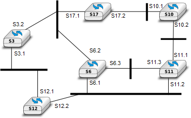
Fig. 1. A small network composed of Ethernet switches
Consider the switched network shown in Fig. 1. In this network, assume that the LAN between switches S3 and S12 fails. How should the switches update their port/address tables after the link failure ?
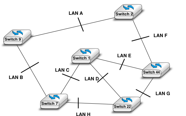
Consider the switched network shown in the figure below. Compute the Spanning Tree of this network.
![\tikzstyle{arrow} = [thick,->,>=stealth]
\tikzset{switch/.style = {diamond, draw, text centered, minimum height=2em, node distance= 2cm}, }
\tikzset{router/.style = {rectangle, draw, text centered, minimum height=2em}, }
\tikzset{host/.style = {circle, draw, text centered, minimum height=2em}, }
\tikzset{ftable/.style={rectangle, dashed, draw} }
\node[switch] (S3) {S5};
\node[switch, left of=S3] (S6) {S9};
\node[switch, right of=S3] (S7) {S10};
\node[switch, above of=S3] (S4) {S2};
\node[switch, below of=S3] (S9) {S4};
\path[draw,thick]
(S3) edge (S6)
(S3) edge (S7)
(S6) edge (S4)
(S4) edge (S7)
(S3) edge (S9)
(S9) edge (S7)
(S3) edge (S7);](_images/tikz-b8fefb4548430c80b01b0e823687d7e4cc130a3a.png)
Many enterprise networks are organized with a set of backbone devices interconnected by using a full mesh of links as shown in Fig.2. In this network, what are the benefits and drawbacks of using Ethernet switches and IP routers running OSPF ?
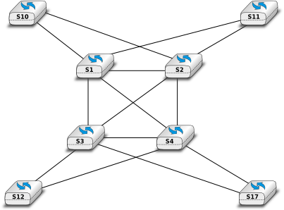
Fig. 2. A typical enterprise backbone network
- In the network depicted in Fig. 3, the host H0 performs a traceroute toward its peer H1 (designated by its name) through a network composed of switches and routers. Explain precisely the frames, packets, and segments exchanged since the network was turned on. You may assign addresses if you need to.
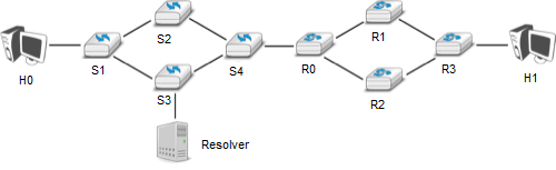
Fig. 3. Host H0 performs a traceroute towards its peer H1 through a network composed of switches and routers
- In the network represented in Fig. 4, can the host H0 communicate with H1 and vice-versa? Explain. Add whatever you need in the network to allow them to communicate.

Fig. 4. Can H0 and H1 communicate ?
- Consider the network depicted in Fig. 5. Both of the hosts H0 and H1 have two interfaces: one connected to the switch S0 and the other one to the switch S1. Will the link between S0 and S1 ever be used? If so, under which assumptions? Provide a comprehensive answer.

Fig. 5. Will the link between S0 and S1 ever be used?
- Most commercial Ethernet switches are able to run the Spanning tree protocol independently on each VLAN. What are the benefits of using per-VLAN spanning trees ?
- Consider the network shown below and assume that all routers use a link-state routing protocol.
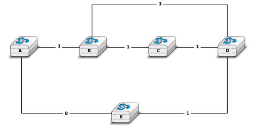
Simple network with redundant links
- Show the messages used by the routers to discover their neighbours and establish adjacencies.
- Show the messages that propagate the adjacencies of A during the flooding phase.
- For each router compute its routing table once the flooding is over.
- Consider that link B-C fails and that router B is the first to detect the failure. Router B will flood its updated link state packet through the entire network and all routers will recompute their forwarding table. Compute the successive updates to the routers RIB, assuming that router C receives the updated link-state packet from router B before detecting the failure himself.
- What would change if routers had used a distance-vector protocol instead.
Netkit STP lab
In the lab lab_stp (/netkit/netkit-lab_stp.zip), you can explore the behavior of a network with switches that use the Spanning Tree Protocol (STP). This protocol allows switches to automatically disable ports on Ethernet switches to ensure that the network does not contain any cycle that could cause frames to loop forever.
Here is the topology of the network:
To use STP, these switches uses brctl, a tool that allows to configure devices as Ethernet bridges and build the spanning tree.
For this lab, you can use the wireshark or tcpdump as packet sniffers.
To launch the lab you have to go in the directory of the lab and launch it with netkit using command lstart (you can add the option -f for a quick launch).
You can see that the 6 machines are launched. For the moment, no one of them runs STP. You will run it (via the brctl command) on two routers and activate wireshark on one of them as explained above. To activate the STP on one switch type in his terminal:
brctl stp br0 on
ifconfig br0 up
With these two routers you can see what messages are exchanged for the root bridge election. You can see the state of a bridge by typing :
brctl showstp br0
This command brings information about the designated root of the tree, the root port of the switch and the cost to the root switch.
Now, you can launch some other switches. By doing that you change the topology. With wireshark you can observe the packets of the spanning tree protocol that are exchanged. The switches already launched will generate a “topology change notification”, then others switches will acknowlegde these changes.
When all switches are launched, you can look at the bridge state of each switches:
brctl showstp br0
You can see wich ports are in blocking state, wich are in forwarding state.
You can also look at the port-station table by entering :
brctl showmacs br0
You can make some links fail and observe what is happening. You can do that by stoping one interface on a switch or the entire bridge (if=br0) :
ifconfig IF down
where IF is the name of your interface.