Warning
This is an unpolished draft of the second edition of this ebook. If you find any error or have suggestions to improve the text, please create an issue via https://github.com/obonaventure/cnp3/issues?milestone=2
Multiple choice questions
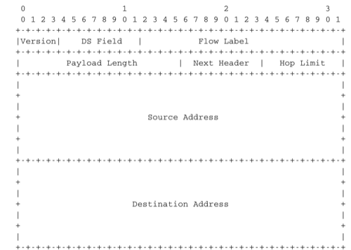
The IPv6 packet header includes several fields that are shown in the figure below.
A router never changes any field of an IPv6 packet that it forwards.
When a host sends an IPv6 packet, its HopLimit is always set to zero. Routers increment the value of this field for each packet that they forward.
A router always decrements the HopLimit of all forwarded IPv6 packets.
To forward a packet, a router always looksup the destination address inside its forwarding table.
- The IPv6 addresses are 128 bits wide and can be represented by using the hexadecimal representation defined in RFC 5952.
2001:db8:a:bb:cc:ddd:eeee::1
2001:db8:a:bb:cc:ddddd::1
2001:db8:a:bb::cc:ddd::1
..comment:: This address is invalid. An IPv6 address cannot contain twice two consecutive semicolumns ::
2001:dg8:1234:abcd::cafe
2001:dead:beef:bad:cafe:1234:abcd:cafe:1
- Among the textual representation for IPv6 addresses below, select all the ones that correspond to IPv6 address 2001:db8:0:0:a::cafe.
2001:0db8::a::cafe
2001:db8:0:0:a000::cafe
2001:db80:0:0:a::cafe
- The forwarding tables used in an IPv6 network define the forwarding paths that are used for the packets. Consider the simple network depicted in the figure below. In this network, the hosts have the following addresses :
- host A : 2001:db8:1341:1::A and its default route points to 2001:db8:1341:1::1
- host B : 2001:db8:1341:3::B and its default route points to 2001:db8:1341:3::3
The routers have one address inside each network :
- router R1 uses address 2001:db8:1341:1::1 on its West interface, address 2001:db8:1341:12::1 on its East interface and address 2001:db8:1341:13::1 on its South interface
- router R2 uses address 2001:db8:1341:12::2 on its West interface and address 2001:db8:1341:23::2 on its South-West interface
- router R3 uses address 2001:db8:1341:3::3 on its East interface, address 2001:db8:1341:23::3 on its North-East interface and address 2001:db8:1341:13::3 on its North interface
The forwarding tables of these three routers, ignoring the routes to the local interfaces, are shown in the figure below.
![\tikzstyle{arrow} = [thick,->,>=stealth]
\tikzset{router/.style = {rectangle, draw, text centered, minimum height=2em}, }
\tikzset{host/.style = {circle, draw, text centered, minimum height=2em}, }
\tikzset{ftable/.style={rectangle, dashed, draw} }
\node[host] (A) {A};
\node[router, right=of A] (R1) { R1 };
\node[ftable, above=of R1] (FR1) { \begin{tabular}{l|l}
Dest. & Nexthop \\
\hline
2001:db8:1341:3/64 & 2001:db8:1341:12::2 \\
2001:db8:1341:23/64 & 2001:db8:1341:13::3 \\
\end{tabular}};
\node[router,right=of R1] (R2) {R2};
\node[ftable, right=of R2] (FR2) { \begin{tabular}{l|l}
Dest. & Nexthop \\
\hline
2001:db8:1341:3/64 & 2001:db8:1341:23::3 \\
2001:db8:1341:1/64 & 2001:db8:1341:12::1 \\
2001:db8:1341:13/64 & 2001:db8:1341:23::3 \\
\end{tabular}\\};
\node[router,below=of R1] (R3) {R3};
\node[ftable, below=of R3] (FR3) { \begin{tabular}{l|l}
Dest. & Nexthop \\
\hline
2001:db8:1341:1/64 & 2001:db8:1341:13::1 \\
2001:db8:1341:12/64 & 2001:db8:1341:23::2 \\
\end{tabular}\\};
\node[host, right=of R3] (B) {B};
\path[draw,thick]
(A) edge (R1)
(R1) edge (R2)
(R2) edge (R3)
(R1) edge (R3)
(R3) edge (B);
\draw[arrow, dashed] (FR1) -- (R1);
\draw[arrow, dashed] (FR2) -- (R2);
\draw[arrow, dashed] (FR3) -- (R3);](_images/tikz-51fbae37277244cc0d5fa7c5271422887fc679ad.png)
![\tikzstyle{arrow} = [thick,->,>=stealth]
\tikzset{router/.style = {rectangle, draw, text centered, minimum height=2em}, }
\tikzset{host/.style = {circle, draw, text centered, minimum height=2em}, }
\tikzset{ftable/.style={rectangle, dashed, draw} }
\node[host] (A) {A};
\node[router, right=of A] (R1) { R1 };
\node[router,right=of R1] (R2) {R2};
\node[router,below=of R1] (R3) {R3};
\node[host, right=of R3] (B) {B};
\draw[arrow, color=red] (A) -- (R1);
\draw[arrow, color=red] (R1) -- (R2);
\draw[arrow, color=red] (R2) -- (R3);
\draw[arrow, color=red] (R3) -- (B);](_images/tikz-bb3f0fca6ea29088154aebdd25fb3eed5e345736.png)
![\tikzstyle{arrow} = [thick,->,>=stealth]
\tikzset{router/.style = {rectangle, draw, text centered, minimum height=2em}, }
\tikzset{host/.style = {circle, draw, text centered, minimum height=2em}, }
\tikzset{ftable/.style={rectangle, dashed, draw} }
\node[host] (A) {A};
\node[router, right=of A] (R1) { R1 };
\node[router,right=of R1] (R2) {R2};
\node[router,below=of R1] (R3) {R3};
\node[host, right=of R3] (B) {B};
\draw[arrow, color=red] (B) -- (R3);
\draw[arrow, color=red] (R3) -- (R2);
\draw[arrow, color=red] (R2) -- (R1);
\draw[arrow, color=red] (R1) -- (A);](_images/tikz-82d882b45e0c00690fd076e4d5f25771dab91511.png)
![\tikzstyle{arrow} = [thick,->,>=stealth]
\tikzset{router/.style = {rectangle, draw, text centered, minimum height=2em}, }
\tikzset{host/.style = {circle, draw, text centered, minimum height=2em}, }
\tikzset{ftable/.style={rectangle, dashed, draw} }
\node[host] (A) {A};
\node[router, right=of A] (R1) { R1 };
\node[router,right=of R1] (R2) {R2};
\node[router,below=of R1] (R3) {R3};
\node[host, right=of R3] (B) {B};
\draw[arrow, color=red] (A) -- (R1);
\draw[arrow, color=red] (R1) -- (R3);
\draw[arrow, color=red] (R3) -- (B);](_images/tikz-b73be0186e6f8244756157bc04cd24c8f685d78d.png)
![\tikzstyle{arrow} = [thick,->,>=stealth]
\tikzset{router/.style = {rectangle, draw, text centered, minimum height=2em}, }
\tikzset{host/.style = {circle, draw, text centered, minimum height=2em}, }
\tikzset{ftable/.style={rectangle, dashed, draw} }
\node[host] (A) {A};
\node[router, right=of A] (R1) { R1 };
\node[router,right=of R1] (R2) {R2};
\node[router,below=of R1] (R3) {R3};
\node[host, right=of R3] (B) {B};
\draw[arrow, color=red] (B) -- (R3);
\draw[arrow, color=red] (R3) -- (R1);
\draw[arrow, color=red] (R1) -- (A);](_images/tikz-45f908abedce75652b402786d30210ec1e72e8fb.png)
- Consider the network shown in the figure below. In this network, the following addresses are used.
- host A : 2001:db8:1341:1::A and its default route points to 2001:db8:1341:1::1
- host B : 2001:db8:1341:4::B and its default route points to 2001:db8:1341:4::4
The routers have one address inside each network :
- router R1 uses address 2001:db8:1341:1::1 on its West interface, address 2001:db8:1341:12::1 on its East interface and address 2001:db8:1341:13::1 on its South interface
- router R2 uses address 2001:db8:1341:12::2 on its West interface, address 2001:db8:1341:23::2 on its South-West interface and address 2001:db8:1341:24::2 on its South interface.
- router R3 uses address 2001:db8:1341:34::3 on its East interface, address 2001:db8:1341:23::3 on its North-East interface and address 2001:db8:1341:13::3 on its North interface
- router R4 uses address 2001:db8:1341:34::4 on its West interface, address 2001:db8:1341:24::4 on its North interface and address 2001:db8:1341:4::4 on its East interface
The forwarding paths used in a network depend on the forwarding tables installed in the network nodes. Sometimes, these forwarding tables must be configured manually.
![\tikzstyle{arrow} = [thick,->,>=stealth]
\tikzset{router/.style = {rectangle, draw, text centered, minimum height=2em}, }
\tikzset{host/.style = {circle, draw, text centered, minimum height=2em}, }
\tikzset{ftable/.style={rectangle, dashed, draw} }
\node[host] (A) {A};
\node[router, right=of A] (R1) { R1 };
\node[ftable, above=of R1] (FR1) { \begin{tabular}{l|l}
Dest. & Nexthop \\
\hline
2001:db8:1341:4/64 & 2001:db8:1341:12::2 \\
2001:db8:1341:23/64 & 2001:db8:1341:13::3 \\
2001:db8:1341:34/64 & 2001:db8:1341:13::3 \\
2001:db8:1341:24/64 & 2001:db8:1341:12::2 \\
\end{tabular}};
\node[router,right=of R1] (R2) {R2};
\node[router,below=of R1] (R3) {R3};
\node[router,below=of R2] (R4) {R4};
\node[ftable,below=of R4] (FR4) { \begin{tabular}{l|l}
Dest. & Nexthop \\
\hline
2001:db8:1341:1/64 & 2001:db8:1341:34::3 \\
2001:db8:1341:23/64 & 2001:db8:1341:24::2 \\
2001:db8:1341:13/64 & 2001:db8:1341:34::3 \\
2001:db8:1341:12/64 & 2001:db8:1341:24::2 \\
\end{tabular}\\};
\node[host, right=of R4] (B) {B};
\path[draw,thick]
(A) edge (R1)
(R1) edge (R2)
(R2) edge (R3)
(R1) edge (R3)
(R4) edge (R3)
(R2) edge (R4)
(R4) edge (B);
\draw[arrow, dashed] (FR1) -- (R1);
\draw[arrow, dashed] (FR4) -- (R4);](_images/tikz-ea79ae11eb6cc9c63576561c0f91c3fb693a59e3.png)
New forwarding table for R3:
Dest. Nexthop 2001:db8:1341:1/64 2001:db8:1341:23::2 2001:db8:1341:4/64 2001:db8:1341:34::4 2001:db8:1341:12/64 2001:db8:1341:13::3 2001:db8:1341:24/64 2001:db8:1341:23::2
New forwarding table for R2:
Dest. Nexthop 2001:db8:1341:1/64 2001:db8:1341:12::1 2001:db8:1341:4/64 2001:db8:1341:24::4 2001:db8:1341:13/64 2001:db8:1341:12::1 2001:db8:1341:34/64 2001:db8:1341:23::3
New forwarding table for R3:
Dest. Nexthop 2001:db8:1341:1/64 2001:db8:1341:13::1 2001:db8:1341:4/64 2001:db8:1341:34::4 2001:db8:1341:12/64 2001:db8:1341:13::3 2001:db8:1341:24/64 2001:db8:1341:23::2
New forwarding table for R2:
Dest. Nexthop 2001:db8:1341:1/64 2001:db8:1341:12::1 2001:db8:1341:4/64 2001:db8:1341:23::3 2001:db8:1341:13/64 2001:db8:1341:12::1 2001:db8:1341:34/64 2001:db8:1341:23::3
New forwarding table for R3:
Dest. Nexthop 2001:db8:1341:1/64 2001:db8:1341:34::4 2001:db8:1341:4/64 2001:db8:1341:34::4 2001:db8:1341:12/64 2001:db8:1341:13::3 2001:db8:1341:24/64 2001:db8:1341:23::2
New forwarding table for R2:
Dest. Nexthop 2001:db8:1341:1/64 2001:db8:1341:12::1 2001:db8:1341:4/64 2001:db8:1341:24::4 2001:db8:1341:13/64 2001:db8:1341:12::1 2001:db8:1341:34/64 2001:db8:1341:23::3
New forwarding table for R3:
Dest. Nexthop 2001:db8:1341:1/64 2001:db8:1341:23::2 2001:db8:1341:4/64 2001:db8:1341:34::4 2001:db8:1341:12/64 2001:db8:1341:13::3 2001:db8:1341:24/64 2001:db8:1341:23::2
New forwarding table for R2:
Dest. Nexthop 2001:db8:1341:1/64 2001:db8:1341:23::3 2001:db8:1341:4/64 2001:db8:1341:24::4 2001:db8:1341:13/64 2001:db8:1341:12::1 2001:db8:1341:34/64 2001:db8:1341:23::3
New forwarding table for R3:
Dest. Nexthop 2001:db8:1341:1/64 2001:db8:1341:13::1 2001:db8:1341:4/64 2001:db8:1341:23::2 2001:db8:1341:12/64 2001:db8:1341:13::3 2001:db8:1341:24/64 2001:db8:1341:23::2
New forwarding table for R2:
Dest. Nexthop 2001:db8:1341:1/64 2001:db8:1341:12::1 2001:db8:1341:4/64 2001:db8:1341:23::3 2001:db8:1341:13/64 2001:db8:1341:12::1 2001:db8:1341:34/64 2001:db8:1341:23::3
Consider the same network as in the previous question, but now the forwarding tables of R2 and R3 are configured as shown below :
![\tikzstyle{arrow} = [thick,->,>=stealth]
\tikzset{router/.style = {rectangle, draw, text centered, minimum height=2em}, }
\tikzset{host/.style = {circle, draw, text centered, minimum height=2em}, }
\tikzset{ftable/.style={rectangle, dashed, draw} }
\node[host] (A) {A};
\node[router, right=of A] (R1) { R1 };
\node[router,right=of R1] (R2) {R2};
\node[ftable, above=of R2] (FR2) { \begin{tabular}{l|l}
Dest. & Nexthop \\
\hline
2001:db8:1341:1/64 & 2001:db8:1341:12::1 \\
2001:db8:1341:4/64 & 2001:db8:1341:23::3 \\
2001:db8:1341:13/64 & 2001:db8:1341:23::3 \\
2001:db8:1341:34/64 & 2001:db8:1341:23::3 \\
\end{tabular}};
\node[router,below=of R1] (R3) {R3};
\node[router,below=of R2] (R4) {R4};
\node[ftable,below=of R3] (FR3) { \begin{tabular}{l|l}
Dest. & Nexthop \\
\hline
2001:db8:1341:1/64 & 2001:db8:1341:23::2 \\
2001:db8:1341:4/64 & 2001:db8:1341:34::4 \\
2001:db8:1341:12/64 & 2001:db8:1341:23::2 \\
2001:db8:1341:24/64 & 2001:db8:1341:23::2 \\
\end{tabular}\\};
\node[host, right=of R4] (B) {B};
\path[draw,thick]
(A) edge (R1)
(R1) edge (R2)
(R2) edge (R3)
(R1) edge (R3)
(R4) edge (R3)
(R2) edge (R4)
(R4) edge (B);
\draw[arrow, dashed] (FR2) -- (R2);
\draw[arrow, dashed] (FR3) -- (R3);](_images/tikz-d7488d2e81d6aabd69a07a5edf6c354982b763c2.png)
New forwarding table for R1:
Dest. Nexthop 2001:db8:1341:4/64 2001:db8:1341:12::2 2001:db8:1341:23/64 2001:db8:1341:13::3 2001:db8:1341:24/64 2001:db8:1341:12::2 2001:db8:1341:34/64 2001:db8:1341:13::3
New forwarding table for R4:
Dest. Nexthop 2001:db8:1341:1/64 2001:db8:1341:34::4 2001:db8:1341:13/64 2001:db8:1341:34::3 2001:db8:1341:12/64 2001:db8:1341:24::2 2001:db8:1341:23/64 2001:db8:1341:24::2
New forwarding table for R1:
Dest. Nexthop 2001:db8:1341:4/64 2001:db8:1341:13::3 2001:db8:1341:23/64 2001:db8:1341:12::2 2001:db8:1341:24/64 2001:db8:1341:12::2 2001:db8:1341:34/64 2001:db8:1341:13::3
New forwarding table for R4:
Dest. Nexthop 2001:db8:1341:1/64 2001:db8:1341:24::2 2001:db8:1341:13/64 2001:db8:1341:34::3 2001:db8:1341:12/64 2001:db8:1341:24::2 2001:db8:1341:23/64 2001:db8:1341:24::2
New forwarding table for R1:
Dest. Nexthop 2001:db8:1341:4/64 2001:db8:1341:12::2 2001:db8:1341:23/64 2001:db8:1341:13::3 2001:db8:1341:24/64 2001:db8:1341:12::2 2001:db8:1341:34/64 2001:db8:1341:13::3
New forwarding table for R4:
Dest. Nexthop 2001:db8:1341:1/64 2001:db8:1341:24::2 2001:db8:1341:13/64 2001:db8:1341:34::3 2001:db8:1341:12/64 2001:db8:1341:24::2 2001:db8:1341:23/64 2001:db8:1341:24::2
- Consider again the same network with three routers as discussed earlier. Let us know explore how traceroute6(8) operates in such a network. A key point to remember about traceroute6(8) is that when it returns an ICMP message, this message is sent inside a packet whose source is one of the addresses of the router and whose destination is the source address of the packet that triggered the generation of this ICMP message. In this network, the hosts have the following addresses :
- host A : 2001:db8:1341:1::A and its default route points to 2001:db8:1341:1::1
- host B : 2001:db8:1341:3::B and its default route points to 2001:db8:1341:3::3
The routers have one address inside each network :
- router R1 uses address 2001:db8:1341:1::1 on its West interface, address 2001:db8:1341:12::1 on its East interface and address 2001:db8:1341:13::1 on its South interface
- router R2 uses address 2001:db8:1341:12::2 on its West interface and address 2001:db8:1341:23::2 on its South-West interface
- router R3 uses address 2001:db8:1341:3::3 on its East interface, address 2001:db8:1341:23::3 on its North-East interface and address 2001:db8:1341:13::3 on its North interface
The forwarding tables of these three routers, ignoring the routes to the local interfaces, are shown in the figure below.
traceroute6 to 2001:db8:1341:1::A from 2001:db8:1341:3::B
1  2001:db8:1341:3::3
2  2001:db8:1341:13::1
3  2001:db8:1341:1::A
traceroute6 to 2001:db8:1341:1::A from 2001:db8:1341:3::B
1  2001:db8:1341:3::3
2  2001:db8:1341:23::2
3  2001:db8:1341:12::1
4  2001:db8:1341:1::A
traceroute6 to 2001:db8:1341:3::B from 2001:db8:1341:1::A
1  2001:db8:1341:1::1
2  2001:db8:1341:13::3
3  2001:db8:1341:3::B
traceroute6 to 2001:db8:1341:3::B from 2001:db8:1341:1::A
1  2001:db8:1341:1::1
2  2001:db8:1341:12::2
3  2001:db8:1341:23::3
4  2001:db8:1341:3::B
- When manipulating IPv6 address, it is sometimes necessary to convert an IPv6 address in its binary representation.
00100000 00000001 00001101 10111000 00010011 01000001 11111100 10000001
00000000 00000000 00000000 00000000 00000000 00000000 00000000 00000001
00000000 00000000 00000000 00000000 00000000 00000000 00000000 00000001
00100000 00000001 00001101 10111000 00010011 01000001 11111100 10000001
00000001 00100000 10111000 00001101 010000000010011 1 10000001 11111100
00000000 00000000 00000000 00000000 00000000 00000000 00000000 00000001
00100000 00000001 11011011 10000000 00010011 01000001 11111100 10000001
00000000 00000000 00000000 00000000 00000000 00000000 00000000 00000001
- When an IPv6 router receives a packet to be forwarded, it finds the most specific match for the destination address of this packet in its forwarding table. Consider the following forwarding table from an hypothetical IPv6 router.
2001:DB8:1341::/48, via nexthop1
2001:DB8:1341:2000/51, via nexthop5
2001:DB8:1341:2000/64, interface1
2001:DB8:1341:4000/50, via nexthop2
2001:DB8:1341:5000/52, nexthop3
2001:DB8:1341:7000/64, interface2
2001:DB8:1341:5555/64, interface3
2001:DB8::/16 via nexthop4
::/0 via nexthop0
A packet whose destination address is 2001:DB8:1342:5555::1 will be forwarded via nexthop4
A packet whose destination address is 2001:DB8:1342:5555::1 will be forwarded via interface3
A packet whose destination address is 2001:DB8:1341:3000::1 will be forwarded via nexthop5
A packet whose destination address is 2001:DB8:1341:3000::1 will be forwarded via nexthop0
A packet whose destination address is 2001:DB8:1341:3000::1 will be forwarded via nexthop1
A packet whose destination address is 2001:DB8:1341:6000::1 will be forwarded via nexthop2
A packet whose destination address is 2001:DB8:1341:6000::1 will be forwarded via nexthop0
A packet whose destination address is 2001:DB8:1341:6000::1 will be forwarded via nexthop1
A packet whose destination address is 2001:DB8:1341:5000::1 will be forwarded via nexthop3
A packet whose destination address is 2001:DB8:1341:5000::1 will be forwarded via nexthop2
A packet whose destination address is 2001:DB8:1341:5000::1 will be forwarded via nexthop1
Design questions
- Consider the network shown in the figure below. In this network, the following addresses are used.
- host A : 2001:db8:1341:1::A and its default route points to 2001:db8:1341:1::1
- host B : 2001:db8:1341:4::B and its default route points to 2001:db8:1341:4::4
The routers have one address inside each network :
- router R1 uses address 2001:db8:1341:1::1 on its West interface, address 2001:db8:1341:12::1 on its East interface and address 2001:db8:1341:13::1 on its South interface
- router R2 uses address 2001:db8:1341:12::2 on its West interface, and address 2001:db8:1341:24::2 on its South interface
- router R3 uses address 2001:db8:1341:34::3 on its East interface and address 2001:db8:1341:13::3 on its North interface
- router R4 uses address 2001:db8:1341:34::4 on its West interface, address 2001:db8:1341:24::4 on its North interface and address 2001:db8:1341:4::4 on its East interface
Routers R2 and R3 are buggy in this network. Besides the routes for their local interfaces (not shown in the figure), they only have a default route which is shown in the figure below.
![\tikzstyle{arrow} = [thick,->,>=stealth]
\tikzset{router/.style = {rectangle, draw, text centered, minimum height=2em}, }
\tikzset{host/.style = {circle, draw, text centered, minimum height=2em}, }
\tikzset{ftable/.style={rectangle, dashed, draw} }
\node[host] (A) {A};
\node[router, right=of A] (R1) { R1 };
\node[ftable, above=of R1] (FR2) { \begin{tabular}{l|l}
Dest. & Nexthop \\
\hline
::/0 & 2001:db8:1341:12::1 \\
\end{tabular}};
\node[router,right=of R1] (R2) {R2};
\node[router,below=of R1] (R3) {R3};
\node[router,below=of R2] (R4) {R4};
\node[ftable,below=of R4] (FR3) { \begin{tabular}{l|l}
Dest. & Nexthop \\
\hline
::/0 & 2001:db8:1341:34::4 \\
\end{tabular}\\};
\node[host, right=of R4] (B) {B};
\path[draw,thick]
(A) edge (R1)
(R1) edge (R2)
(R1) edge (R3)
(R4) edge (R3)
(R2) edge (R4)
(R4) edge (B);
\draw[arrow, dashed] (FR2) -- (R2);
\draw[arrow, dashed] (FR3) -- (R3);](_images/tikz-8c2a5af248a8544d55a754ffd91228a5d2e4c78f.png)
How do you configure the forwarding tables on R1 and R4 so that A can reach B and the reverse ?
Consider a slightly different network than in the previous question.
![\tikzstyle{arrow} = [thick,->,>=stealth]
\tikzset{router/.style = {rectangle, draw, text centered, minimum height=2em}, }
\tikzset{host/.style = {circle, draw, text centered, minimum height=2em}, }
\tikzset{ftable/.style={rectangle, dashed, draw} }
\node[host] (A) {A};
\node[router, right=of A] (R1) { R1 };
\node[router,right=of R1] (R2) {R2};
\node[router,below=of R1] (R3) {R3};
\node[router,below=of R2] (R4) {R4};
\node[host, right=of R4] (B) {B};
\path[draw,thick]
(A) edge (R1)
(R1) edge (R2)
(R1) edge (R3)
(R1) edge (R4)
(R4) edge (R3)
(R2) edge (R4)
(R4) edge (B);](_images/tikz-7c78d09cc2bca8dc9db4c3dbefdda6472ea30d6a.png)
Assuming that the following IPv6 addresses are used :
- host A : 2001:db8:1341:1::A and its default route points to 2001:db8:1341:1::1
- host B : 2001:db8:1341:4::B and its default route points to 2001:db8:1341:4::4
The routers have one address inside each network :
- router R1 uses address 2001:db8:1341:1::1 on its West interface, address 2001:db8:1341:12::1 on its East interface, address 2001:db8:1341:14::1 on its South-East interface and address 2001:db8:1341:13::1 on its South interface
- router R2 uses address 2001:db8:1341:12::2 on its West interface, and address 2001:db8:1341:24::2 on its South interface
- router R3 uses address 2001:db8:1341:34::3 on its East interface and address 2001:db8:1341:13::3 on its North interface
- router R4 uses address 2001:db8:1341:34::4 on its West interface, address 2001:db8:1341:24::4 on its North interface, address 2001:db8:1341:14::4 on its North-West interface and address 2001:db8:1341:4::4 on its East interface
Can you configure the forwarding tables so that the following paths are used by packets sent by host A to reach one of the four addresses of router R4?
Do your forwarding tables impose the path used to reach host B which is attached to router R4 or do you need to configure an additional entry in these tables ?
![\tikzstyle{arrow} = [thick,->,>=stealth]
\tikzset{router/.style = {rectangle, draw, text centered, minimum height=2em}, }
\tikzset{host/.style = {circle, draw, text centered, minimum height=2em}, }
\tikzset{ftable/.style={rectangle, dashed, draw} }
\node[host] (A) {A};
\node[router, right=of A] (R1) { R1 };
\node[router,right=of R1] (R2) {R2};
\node[router,below=of R1] (R3) {R3};
\node[router,below=of R2] (R4) {R4};
\node[host, right=of R4] (B) {B};
\path[draw,arrow, color=red, thick]
(A) edge (R1)
(R1) edge (R2)
(R2) edge (R4);](_images/tikz-8610370c587fbb15d7b0a1f795d7935a26cb615a.png)
![\tikzstyle{arrow} = [thick,->,>=stealth]
\tikzset{router/.style = {rectangle, draw, text centered, minimum height=2em}, }
\tikzset{host/.style = {circle, draw, text centered, minimum height=2em}, }
\tikzset{ftable/.style={rectangle, dashed, draw} }
\node[host] (A) {A};
\node[router, right=of A] (R1) { R1 };
\node[router,right=of R1] (R2) {R2};
\node[router,below=of R1] (R3) {R3};
\node[router,below=of R2] (R4) {R4};
\node[host, right=of R4] (B) {B};
\path[draw,arrow, color=blue, thick]
(A) edge (R1)
(R1) edge (R4);](_images/tikz-c3bfb41fde435f9f5f0bd6bfcb3170cf925c491d.png)
![\tikzstyle{arrow} = [thick,->,>=stealth]
\tikzset{router/.style = {rectangle, draw, text centered, minimum height=2em}, }
\tikzset{host/.style = {circle, draw, text centered, minimum height=2em}, }
\tikzset{ftable/.style={rectangle, dashed, draw} }
\node[host] (A) {A};
\node[router, right=of A] (R1) { R1 };
\node[router,right=of R1] (R2) {R2};
\node[router,below=of R1] (R3) {R3};
\node[router,below=of R2] (R4) {R4};
\node[host, right=of R4] (B) {B};
\path[draw,arrow, color=green, thick]
(A) edge (R1)
(R1) edge (R3)
(R3) edge (R4);](_images/tikz-6267e5460ea0810164d9bb001eeec0cd6afb5de4.png)
- Consider the network below that contains only routers. This network has been configured by a group of students and you must verify whether the configuration is correct. All the IPv6 addresses are part of the same /48 prefix that we name p. The following subnets are defined in this /48 prefix.
p:12/64 for the link between R1 and R2. On this subnet, R1 uses address p:12::1 while router R2 uses address p:12::2
p:13/64 for the link between R1 and R3. On this subnet, R1 uses address p:13::1 while router R3 uses address p:13::3
p:24/64 for the link between R2 and R4. On this subnet, R2 uses address p:24::2 while router R4 uses address p:24::4
...
![\tikzstyle{arrow} = [thick,->,>=stealth]
\tikzset{router/.style = {rectangle, draw, text centered, minimum height=2em}, }
\tikzset{host/.style = {circle, draw, text centered, minimum height=2em}, }
\tikzset{ftable/.style={rectangle, dashed, draw} }
\node[router] (R1) {R1};
\node[router,right=of R1] (R2) {R2};
\node[router,right=of R2] (R5) {R5};
\node[router,below=of R1] (R3) {R3};
\node[router,below=of R2] (R4) {R4};
\node[router,below=of R5] (R6) {R6};
\path[draw,thick]
(R1) edge (R2)
(R1) edge (R3)
(R4) edge (R3)
(R2) edge (R4)
(R2) edge (R5)
(R4) edge (R6)
(R5) edge (R6);](_images/tikz-cc52040303ac833eafac6a0e6ab0a7303f0e4ed5.png)
The students have configured the following forwarding tables on these six routers.
on router R1
on router R2
on router R3
on router R5
on router R4
on router R6
![\tikzset{ftable/.style={rectangle, dashed, draw} }
\node[ftable] (FR1) { \begin{tabular}{l|l}
Dest. & Nexthop/Interface \\
\hline
::/0 & p:12::2 \\
p:12::/64 & East \\
p:13::/64 & South\\
p:25::/64 & p:12::2\\
p:34::/64 & p:12::2\\
\end{tabular}};](_images/tikz-1e7f649c57e75171295628fc05dab5d2c60c1101.png)
![\tikzset{ftable/.style={rectangle, dashed, draw} }
\node[ftable] (FR2) { \begin{tabular}{l|l}
Dest. & Nexthop/Interface \\
\hline
::/0 & p:12::1 \\
p:12::/64 & West \\
p:13::/64 & p:24::4\\
p:24::/64 & South\\
p:25::/64 & East\\
p:56::/64 & p:24::4\\
\end{tabular}};](_images/tikz-7eb55193127d097fb096559cc6207d84cc3b4480.png)
![\tikzset{ftable/.style={rectangle, dashed, draw} }
\node[ftable] (FR3) { \begin{tabular}{l|l}
Dest. & Nexthop/Interface \\
\hline
::/0 & p:13::1\\
p:13::/64 & North \\
p:34::/64 & East\\
p:56::/64 & p:34::4\\
\end{tabular}};](_images/tikz-3d22f7a1be43b48f58de60f01990ad52700b506f.png)
![\tikzset{ftable/.style={rectangle, dashed, draw} }
\node[ftable] (FR5) { \begin{tabular}{l|l}
Dest. & Nexthop/Interface \\
\hline
::/0 & p:56::6 \\
p:12::/64 & p:25::2\\
p:25::/64 & West \\
p:56::/64 & South\\
\end{tabular}};](_images/tikz-96d4d327792bb5ab3877198555aae616c7f20e11.png)
![\tikzset{ftable/.style={rectangle, dashed, draw} }
\node[ftable] (FR4) { \begin{tabular}{l|l}
Dest. & Nexthop/Interface \\
\hline
p:12::/63 & p:24::2\\
p:24::/64 & North\\
p:25::/64 & p:46::6\\
p:34::/64 & West\\
p:46::/64 & East\\
\end{tabular}};](_images/tikz-7415507c1cdc7ce284d4ff0e90f5dd05f19e66e2.png)
![\tikzset{ftable/.style={rectangle, dashed, draw} }
\node[ftable] (FR6) { \begin{tabular}{l|l}
Dest. & Nexthop/Interface \\
\hline
::/0 & p:56::5 \\
p:13::/64 & p:46::4\\
p:24::/63 & p:46::4\\
p:34::/64 & p:46::4\\
p:46::/64 & West\\
p:56::/64 & North\\
\end{tabular}};](_images/tikz-af256f9516afcf3d00b668c5aebcf576ba44266d.png)
Sometimes, static routes must be configured on networks to enforce certain paths. Consider the six routers network shown in the figure below.
![\tikzstyle{arrow} = [thick,->,>=stealth]
\tikzset{router/.style = {rectangle, draw, text centered, minimum height=2em}, }
\tikzset{host/.style = {circle, draw, text centered, minimum height=2em}, }
\tikzset{ftable/.style={rectangle, dashed, draw} }
\node[host] (A1) {A1};
\node[router, right=of A1] (R1) {R1};
\node[host, below=of A1] (A2) {A2};
\node[router,right=of R1] (R2) {R2};
\node[router,right=of R2] (R5) {R5};
\node[router,below=of R1] (R3) {R3};
\node[router,below=of R2] (R4) {R4};
\node[router,below=of R5] (R6) {R6};
\node[host, right=of R5] (B1) {B1};
\node[host, right=of R6] (B2) {B2};
\path[draw,thick]
(A1) edge (R1)
(A2) edge (R3)
(R1) edge (R2)
(R1) edge (R3)
(R4) edge (R3)
(R2) edge (R4)
(R2) edge (R5)
(R4) edge (R6)
(R5) edge (R6)
(R5) edge (B1)
(R6) edge (B2);](_images/tikz-1ca1c5050a4cea7480f11e17671b2ccb863d03b6.png)
In this network, we will focus on four IPv6 prefixes :
- p:0000::/64 used on the link A1-R1. A1 uses address p:0000::A1/64
- p:0001::/64 used on the link A2-R3. A2 uses address p:0001::A2/64
- p:0002::/64 used on the link B1-R5. B1 uses address p:0002::B1/64
- p:0003::/64 used on the link B2-R6. B2 uses address p:0003::B2/64
Can you configure the forwarding tables of the six routers to achieve the following network objectives :
- All packets sent by B1 and B2 to A1 and A2 are always forwarded via R2 while all packets from A1 and A2 are always forwarded via R4
- The packets whose destinations are A1, A2, B1 or B2 are never forwarded via router R4
- The packets sent by A1 or A2 towards B1 are always forwarded via R2 while the packets towards B2 are always forwarded via R4.
When creating these forwarding tables, try to minimise the number of entries that you install on each router.
When a network is designed, an important element of the design is the IP address allocation plan. A good allocation plan can provide flexibility and help to reduce the size of the forwarding tables.
![\tikzstyle{arrow} = [thick,->,>=stealth]
\tikzset{router/.style = {rectangle, draw, text centered, minimum height=2em}, }
\tikzset{host/.style = {circle, draw, text centered, minimum height=2em}, }
\tikzset{ftable/.style={rectangle, dashed, draw} }
\node[host] (A1) {A1};
\node[router, right=of A1] (R1) {R1};
\node[host, below=of A1] (A2) {A2};
\node[router,right=of R1] (R2) {R2};
\node[router,right=of R2] (R5) {R5};
\node[router,below=of R1] (R3) {R3};
\node[router,below=of R5] (R6) {R6};
\node[host, right=of R5] (B1) {B1};
\node[host, right=of R6] (B2) {B2};
\path[draw,thick]
(A1) edge (R1)
(A2) edge (R3)
(R1) edge (R3)
(R2) edge (R3)
(R2) edge (R5)
(R2) edge (R6)
(R5) edge (R6)
(R5) edge (B1)
(R6) edge (B2);](_images/tikz-f18b35f47f16939810f6cb75879877b31f8a798e.png)
Assign IP subnets to all links in this network so that you can reduce the number of entries in the forwarding tables of all routers. Assume that you have received a /56 prefix that you can use as you want. Each subnet containing a host must be allocated a /64 subnet.